HowTo: A very simple three step water level indicator for Arduino / ESP
March 31, 2024 @ 06:03
When thinking about my new CanGrow project, which things I want to have data and want to measure, I thought having a water level indicator, for a water tank for example, would be a good idea.
Most things I found were about the premade Waterlevel module, which can be found on ebay, amazon and quite every maker shop. The downside of this module is, that it has a limited length. And I dont want to hack around a module, as my goal for the CanGrow project is, to be very simple.
So I did some further research and thought about those very simple water level indication schematics, which just use a transistor, resistor , led and power source, which brought me also to this arduino projecthub article, which describes how to build such a water level indicator with only a few resistors.
When looking at the schematics, it reminded my heavily to a voltage devicer circuit. So I ignored the “virtual Wheatstone bridge” stuff described in the article and played around a bit and found the solution for my projects problem.
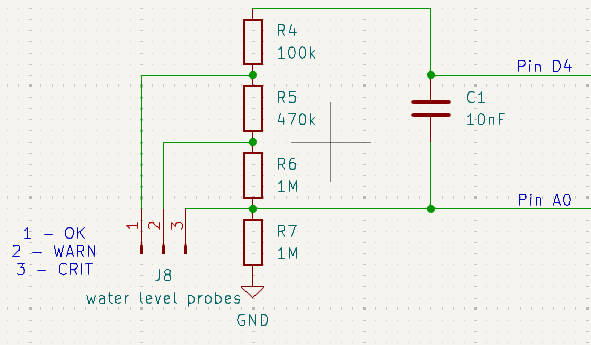
I came up with this schematic:

At the end it is just a voltage divider with a lot of resistors. I could have calculated the resistor values, but I was lazy and went with “try&error” by playing around with CircuitJS
I dont need as much levels to measure, so I just went with three, for Critical, Warning, and OK. This also makes the measurement a bit easier, because there is enough “space” between the single voltages we will read later in our code to clearly differentiate the single levels.
As in the article from Pedro52 described, I also went with a digital Pin of my ESP8266 for the supply voltage of the circuit. This will prevent electrolysis effect, because the voltage only needs to be applied when measuring. Otherwise there will be a constant current flow, which we do not want.
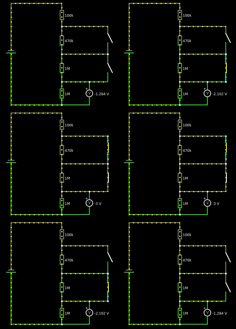
The conductivity of the water will bridge the single probes when being in contact with the water. This results in a lower resistance and the voltage will raise. I simulated the functionality in CircuitJS for demonstration:

Now the only thing left is to get the values. For this we just need to read the voltage with the analog Pin of the ESP8266 (in my case, applies as well for any other like Arduino UNO, ESP32… ). In my CanGrow project, I wrote a little function for that.
// digital PIN for supply voltage
int PINwater = D4;
// analog PIN to read the values
int PINAwater = A0;

int getWaterlevel() {

  /*
  * waterlevelRAW
  * ===========
  * 0 - 199   : CRITICAL
  * 200 - 399 : WARNING
  * >400      : OK
  *
  * waterlevel
  * ==========
  * 2         : CRITICAL
  * 1         : WARNING
  * 0         : OK
  */

  int waterlevelWARN = 200;
  int waterlevelOK = 400;
  int waterlevelRAW = 0;
  int waterlevel = 0;

  // enable Vcc for water level sensor
  digitalWrite(PINwater, HIGH);
  // wait a bit to let the circuit stabilize
  delay(200);
  // get the value
  waterlevelRAW = analogRead(PINAwater);
  // disable Vcc for the sensor to prevent electrolysis effect
  digitalWrite(PINwater, LOW);

  if( waterlevelRAW >= waterlevelOK) {
    waterlevel = 0;
  } else if( waterlevelRAW >= waterlevelWARN) {
    waterlevel = 1;
  } else {
    waterlevel = 2;
  }

  return waterlevel;
}

void setup() {
  // start serial
  Serial.begin(9600);
}

void loop() {
  Serial.print("water status: ");
  // print the value of getWaterlevel() to serial
  Serial.println(getWaterlevel());
  // wait a bit
  delay(300);
}
The raw values I get from the Analog Input on the single levels being in water are
| Probe | Value |
|---|---|
Critical |
132 |
Warning |
242 |
OK |
490 |
So there is enough room to clearly identify the single levels.
And this is it! Now we have a functioning, very simple water level indicator which can measure three levels. If you want, you can add additional probes/levels. You just need to add more resistors to the voltage divider and figure out which values for the resistors you have to use. But with CircuitJS, this should be an easy task, even when you are such a math-lazy-noob creature like me![]()
Have a lot of fun with it, I hope this is useful for someone![]()
When building this circuit, please keep in mind that the values for the resistors and so on I used, are taken with a supply voltage of 3.3V. If you are using an Arduino Uno for example, which works with 5V by default and only has a 10 bit ADC (Analog input), then you have to find out the values for this case. But I think the resistor values can keep the same.
